


 Hide All
You can select vertices, edges, planes, axes, faces, surfaces, rounds, solids, and components in 3D. In 2D, you can select points and lines. You can also select circle and ellipse centers, the midpoints of lines and edges, and the internal points and end points of splines.
You can select components and other objects in the Structure tree and use the Selection panel to select objects in the same part that are similar or related to the object currently selected.
Objects that can’t be selected are dimmed in the Design window.
Your selection list is shown in the status bar at the bottom of the DesignSpark Mechanical window. Status bar labels display both pre-selected and selected objects. Hover over the status message for a detailed list of what you have pre-selected or selected, including primary and secondary (Alt+selected) objects.
Select modes
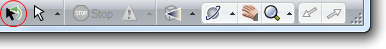
You can click the arrow on the Select tool to use the following optional modes:
-
Using Box: Click and hold the mouse button while drawing a box in the Design window. If you draw the box from left to right, all objects fully enclosed within the box will be selected. If you draw the box from right to left, all objects touching the box will be selected.
-
Using Lasso: Click and hold the mouse button while drawing a freeform shape. All objects fully enclosed by the shape will be selected.
-
Using Polygon: Click and move the mouse to draw a line, then click again to draw the next connecting line, so that you create a polygon shape around the area you want to select.
-
Using Paint: Click and hold the mouse button while highlighting adjacent faces and edges. All edges and faces that you move the mouse over will be selected. Release the mouse button to finalize your selection.
-
Using Boundary: Select faces or edges that define a boundary, click the Select Seed tool guide, and click any object within the boundary. All objects from that seed object to the boundary are selected.
No matter which mode you use, the objects that will be selected are highlighted to preview your selection. You can use the Selection filter to control what gets selected. To select or deselect all available filters, select the All checkbox.
 |
If you entered the Design tab with sheet metal features selected, the Select tool will work as it does in Sheet metal. Right click on the sheet metal part in the Structure tree and choose Suspend Sheet Metal in the context menu. |
To select
The most commonly used selection methods are:
-
Click to select an object.
-
Double-click to select an edge loop. (Double-click again to cycle through alternate loops.)
-
Triple-click to select a solid.
-
Drag (or select Using Box from the Select tool menu) to create a selection box.
-
Press Ctrl+A to select all similar objects, such as faces, edges, or points on the same solid or surface part. For example, if you have a sketch curve selected when you press Ctrl+A, then only sketch curves will be selected.
-
Hold Ctrl and select to add or remove items from the selection. Ctrl with box-selection toggles the selection; Shift with box-selection adds to the selection.
-
Hold Alt and select to create a secondary selection set.
|
Only visible objects are selected with double or triple click. Objects hidden in the Structure tree are not selected. |
|
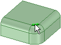
Click once to select a face: |
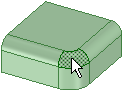 |
|
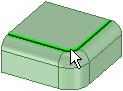
Double-click to select and cycle through chains of similar, connected faces (face loops): |
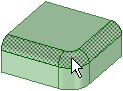 |
|
Triple-click to select a solid: |
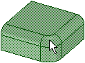 |
|
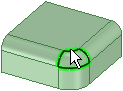
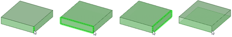
Click once to select an edge: |
 |
|
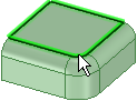
Double-click to select and cycle through chains of connected edges (edge loops): |
   |
-
Select the Select tool
 from the Edit ribbon group.
 -
Mouse over the vertices, edges, faces in the workspace to preview the selectable items in your design.
If multiple objects occur at your cursor location, use the scroll wheel or arrow keys to preview each one.
Click to select a vertex, edge, or face in 3D; click to select a line or point in 2D.
To select:
Do this:
All the edges around a face or closed loop
Double-click an edge or line. Double-click again to select the next loop of edges. Repeat as necessary. You can also right-click the edge or line and choose one of the loop options in the Select menu.
When you repeatedly double-click outside surface edges, the selection cycles through open loop, tangent chain, and face loop, then repeats through that list.
All tangent faces
Double-click a face. (Tangent faces are created by rounds or when edges are drawn on a face.)
Contiguous edges or faces
Click one face or edge, then Shift+click another face or edge to select all the faces or edges between the two.
The sides (but not the top and bottom) of a solid
Triple-click the solid and Ctrl+click the top and bottom to remove them from the selection.
A solid or surface body
Triple-click the solid, or right-click on the solid and select Select > Body.
An entire sketch
Triple-click the sketch.
A component
Right-click on the component and select Select > Component. This option is available only when you right-click an object within the active component.
All objects of same type as selected object
Select an object and press Ctrl+A.
All the objects in the active component (except layout surfaces)
Click Select All in the Select tool menu, or right-click and select Select > Select All from the context menu. The types of objects selected depend on whether you are in Sketch, Section, or 3D mode.
Layout surfaces
Click the object in the Structure tree.
Anything within a selection box
See Box-selecting.
A lightweight component
Check the Lightweight Components box in the Options panel. Then right-click and select Select > Component.
The inverse of the current selection (in the active component)
Right-click a selected object and select Select > Inverse Selection.
A protrusion
Right-click on a protrusion and select Select > Protrusion.
A depression
Right-click inside a depression and select Select > Depression.
One member of a pattern
Right-click a pattern member and select Select > Pattern Member.
All members of a pattern
Right-click a pattern member and select Select > All Pattern Members.
Anything partially in a selection box
Click and drag from the lower right to upper left when drawing a selection box.
The inverse of the current box selection
Press and hold Ctrl while box-selecting to toggle the selected state of the objects within the selection.
Objects that are behind other objects ("query selection")
Hold the Ctrl key and turn the mouse wheel.
If any object was part of a group selection used to perform an action, the other parts of the group are highlighted when that object is selected. Click again to select the entire highlighted group.
When selecting within a view on a drawing sheet, you can only select those objects that are on the cross-section plane, or that are within the boundary of a detail view. Box selecting in Sketch mode selects only sketch lines. Box-selecting in Section mode selects only section lines.
(Optional) Ctrl+click and Shift+click to add or remove items from the selection set.
Ctrl+click to add or remove one item from the selection set. Shift+click to add everything between your first click and the Shift+click to the selection. You can add or remove items both in the workspace and on the Structure tree. You can also press Ctrl and drag to add the items within the selection box to the selection.
(Optional) Alt+click to create a secondary selection set.
Hold down the Alt key while performing any of the other selection techniques (double-click, triple-click, Ctrl, Shift) to create the second selection set. Alternate selections are shown in blue, and are used to guide the actions of the Pull and Move tools.
Click any empty space in the Design window or select Clear Selection from the Select tool menu.
Click Revert Selection in the status bar to go back to your previous selection.
This tool is especially useful when you accidentally clear your selection or add the wrong object and want to go back to your previous selection. You can find this tool next to the Selection filter in the status bar, as shown below.
 To select by turning the mouse wheel
- Coincident objects: Objects often appear at the same location in 2D, such as a vertex and end point of a line that are located at the same point in space. When selecting, check that you have selected the correct object by turning the mouse wheel without moving the mouse.
- Edge shared by two surfaces or solids: Mousing over the edge shades the face that will be affected by an action to the edge if you select it. Turn the mouse wheel to switch between the two faces.
- Vertex shared between two edges: Mousing over a vertex shades the edge that will be affected by an action to the vertex if you select it. Turn the mouse wheel to switch between the edges.
- Face of a solid when only the edge is displayed (such as in a drawing sheet view): You can select the face by turning the mouse wheel. The edge becomes a slightly thicker line when the face is highlighted.
-
Edge loops: If Select edge loops using the mouse scroll wheel is selected in the Advanced DesignSpark Mechanical options, scrolling through edge loop choices pre-highlights the selection. Click on the pre-highlighted edge loop to select it.
The up and down arrow keys work the same as the mouse wheel. Mouse over the element you want to select, and press the up or down arrow keys to "scroll" through the possible selections. This is useful if you are on a laptop or when you use a mouse that doesn't have a scroll wheel.
Tool guides
Within the Select tool, the following tool guide is available:
|
|
The Select tool guide is active by default. This tool lets you click, double-click, triple-click, Ctrl+click, Shift+click, and Alt+click to select items. |

Options
The following options are available for sketches:
|
Maintain sketch connectivity |
Keep the connection between a sketch curve and other curves that share its end points. If you deselect this option and move a sketch curve, the curve will move independent of other curves. |
|
Cartesian dimensions |
Select a point in a sketch and then click this option to see Cartesian dimensions from the point. Cartesian dimensions show you the X and Y distances from the point you select. If you don't have a point selected, it shows you the X and Y distances from the origin. When you select a point, the X, Y, and Z locations display in the status bar. |
|
Polar dimensions |
Select a point in a sketch and then click this option to see Polar dimensions from the point. Polar dimensions show you an angle and a distance from the point you select. If you don't have a point selected, it shows you the angle and distance from the origin. |
|
Snap to grid |
Select this option turn snapping on or off while sketching. The cursor will snap to the minor grid spacing increment while you sketch. The defaults are 1mm for Metric and 0.125in for Imperial units. See Units options to change the minor grid spacing. |
|
Snap to angle |
Select this option to turn angle snapping on or off while sketching. The cursor will snap to the angular snap increment while you sketch. The default is 15 degrees. See Snap options to change the angular increment used for snapping. |