


 Hide All
Use the Pull tool to offset, extrude, revolve, sweep, draft, and blend faces; use it to round, chamfer, or extrude edges. You can also drag a point with the Pull tool to draw a line on a sketch plane.
Pulling the apex of a cone changes its height. Pulling through the base plane will invert the cone. Pulling a loop of edges attached to a vertex will create conical faces at the corners when appropriate.
You can select a face, then pull, dragging anywhere to act, or you can click, drag, and release a highlighted face. In general, the result of a pull stays selected or highlighted after the pull operation.
The action of the Pull tool depends on which faces and edges you select to work with, and which faces, planes, or edges you select to drive the change. For example, if you choose to work with a face, then select an edge to "drive" the pull, the Pull tool infers that you want to pivot the face around that edge. When multiple actions can be inferred, you can use the Tool guides to correct the Pull tool's inference. The Pull tool maintains any offset, mirror, pattern, or coaxial relationships.
When you pull a face, there are two main decisions you need to make. The first is to determine the direction you want to pull in. A default direction is offered to you, but it can be overridden using the Direction tool guide. The second is to determine what is going to happen at the edges of the face. By default, the edges of the face are determined by its neighbors, but you can override this behavior by including the edges in your Pull selection to create an extrusion. When you pull, connected chamfers are automatically removed and replaced.
 |
If you entered the Design tab with sheet metal features selected, the Pull tool will work as it does in Sheet metal. To work as usual, right click on the sheet metal part in the Structure tree and choose Suspend Sheet Metal in the context menu. |
To create and edit a solid
-
Click
 Pull in the Edit group on the Design tab or press P.
Mouse over faces and edges in your design to preview the natural Pull direction. If your mouse is over multiple faces or edges, use the scroll wheel to preview the Pull direction for each one.
-
Select the faces, edges, and points you want to pull to create 3D solids or surfaces.
You can right-click in the Design window and select Anchor Pull Handle, then click to anchor the Pull handle on another object. This command is useful when you want to dimension a Pull from a different location than the center of a face.
If the Pull arrow appears gray instead of yellow, then the object is locked and can't be pulled unless you unlock it. To unlock an object, right-click the object in the Structure tree and select Unlock.
-
(Optional) Alt+click to select the face or edge that will drive the change.
You can also select the appropriate tool guide, then click the face, point, or edge. The driving edge or face is shown in blue. If you select the Show cursor arrows DesignSpark Mechanical option, arrows appear to indicate the directions you can move your mouse to edit the selected object.
If you want to use an annotation dimension, see Driving modification with annotation dimensions.
Measurements can also be used to drive modifications.
 To drive modifications with measurements.
- Enter the Pull tool
- Select a face, edge or vertex
- Enter the Measure tool (shortcut is “e”)and measure any single object or measure between two objects
- Click in the Measurement results (hover over measurements to display purple box). Once selected, that single measurement will display on screen with arrows pointing to either object chosen for measurement.
- Click in the highlighted dimension box and modify the value for a one-time adjustment of the model or create a Measurement Group which can be modified at any time.
- Measurement groups can also be created from Area results. Modifying the group then adjusts the model to produce a desired area. For example, create a Measurement group for the area of a side of a box. While pulling the front of the box, you can enter a new area value for the side to complete the Pull.

-
(Optional) Select options from the Options panel, or right-click and select them from the mini-toolbar.
-
Click and drag in the direction of the Pull arrow to create or edit a solid.
-
If the correct pull arrow is not highlighted, press Tab or click the Pull arrow you want to use.
Press Shift to snap while pulling.
Press the spacebar or click on a dimension to enter a value.
To dimension the pull, type the distance you want to pull and press Enter. You can also type a dimension in the dimension box in the mini-toolbar.
You do not have to click and drag on (or even near) the Pull arrow. In fact, we recommend that you move your cursor away from the arrow for more precise control of the pull. The only important input to the Pull tool is the direction in which you are moving the cursor. When you pull, contiguous solids are automatically combined.
If you want to pull in a head-on view, use the ruler at the bottom right corner of the Design window to pull instead of the Pull arrow. Slide the gray bar to the left to subtract material, and to the right to add material.
You can also click the Up To tool guide, then click the object that sets the plane up to which you want to pull. (When pulling an edge, the face does not need to intersect the edge you are pulling.)
If you pull through another object in the same component, the smaller object is merged into the larger one, and receives the larger object's properties. If you pull multiple, touching surfaces, the smaller surfaces are merged into the largest one. Select the No Merge option if you don't want objects merged.
Hold the Ctrl key while pulling to create a copy of the object that is offset by the distance you pull. You can also hold Ctrl while revolving to create a copy of a surface. The influence of neighboring faces is taken into account to trim or extend the edges of the copied face, when appropriate. You can use the Up To tool guide with Ctrl to make a copy, and you can use the Both Sides option to make two copies that are offset in opposite directions from the original. You can also use the Up To tool guide to pull surfaces up to a reference edge.
Press Esc to cancel the Pull.
See the topics in the Table of Contents under Designing > Editing > Pulling for the list of actions you can perform with the Pull tool.
-
Select the faces, edges, and points you want to work with.
In general, pulling a face increases the size of the solid, pulling an edge creates a surface, and pulling a point creates a line or curve.
-
(Optional) Alt+click the face or edge that will drive the pull.
-
Drag in the direction of the Pull arrow.
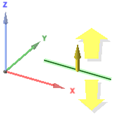
When you select a curve with the Pull tool, the direction of the extrusion is determined by the plane of the curve.
|
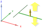
The default direction to pull a curve is along the Z axis. |
 |
|
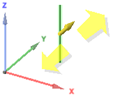
If a curve lies on the Z axis, the pull arrow points in the Y direction. |
 |
|
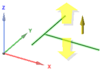
If you select two curves on the same plane, the pull arrow points in the direction that is perpendicular to the plane of the curves. |
 |
|
If you select a curve that touches another curve, the pull arrow points in the direction perpendicular to the plane of the two curves. |
 |
Tool guides
Within the Pull tool, there are several tool guides that let you specify the behavior of the Pull tool:
|
|
The Select tool guide is active by default. When this tool guide is active, you can perform standard selection tasks, and create natural offsets and rounds. Select a face, parallel faces, or surface edges to offset them. Select a solid edge to round it. Alt+click to select the driving face or edge for revolves, directed extrusion, sweeps, and drafts. Alt+double-click an edge to select an edge loop. Alt+double-click again to cycle through alternate edge loops. You can select objects across multiple components to pull. |
|
|
Use the Direction tool guide to select a straight line, edge, axis, origin axis, plane, or planar face to set the pull direction. |
|
|
Select a face to pivot or select a face and edge to revolve. Then use the Revolve tool guide to select the straight line, edge, or axis around which you want to pivot or revolve. |
|
|
Select any number of contiguous faces on the same body, then use the Draft tool guide to select the plane, planar face, or edge around which you want to pivot. None of the contiguous faces can be parallel to the neutral plane, face or edge around which you want to pivot. |
|
|
Use the Sweep tool guide to select the straight or curved lines or edges along which you want to sweep. Faces and edges can be swept, and the sweep trajectory cannot be in the same plane as the face. |
 |
Use the Scale Body tool guide to scale objects in 3D. See Scaling solids and surfaces. |
|
|
Use the Up To tool guide to select the object that you want to pull to. The pulled object's face or edge will mate with the surface of the selected body or be pulled up to a plane through the selection. You can also use this tool guide to pull surfaces up to a reference edge. The object will be copied if you hold Ctrl. |


Pull Options
The following options are available in the Pull tool. Once you select the edge or face to pull, select these options from the Options panel or the mini-toolbar:
|
|
Only add material when you pull. If you pull in a subtractive direction, no change will occur. You can combine this option with other Pull options. |
|
|
Only remove material when you pull. If you pull in an additive direction, no change will occur. You can combine this option with other Pull options. |
|
|
Pulls without merging into other objects even when the object pulled intersects with an existing object. |
|
|
Select a single, detached edge, imprinted edge, or surface, then click this option to pull both sides of the edge or surface at once. |
|
|
Select this option, then click to connect a ruler, oriented along the pull axis, to an anchor edge or face. You can use the ruler to dimension the pull. The direction must be specified to successfully create a ruler dimension. Press Esc to cancel the ruler dimension. |
|
|
Extends an edge or face to the nearest face. This option works similar to the Up To tool guide, except you don't select the face to extend to. You can use this option to automatically pull edges up to the closest faces that intersect with the object. The edges you select are extended in the direction of the Pull handle up to the next set of faces or edges that fully bound the extension. The original surfaces that the edges belong to are extended and new edges may be created; however, new faces are not created. |

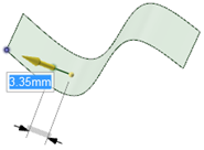
Measure |
Opens the Measure tool. Selecting a measurement result returns you to the Pull tool and displays the measurement value in a dimension box with an arrow pointing to the measured object. Modify the value for a one-time adjustment of the model or create a Measurement Group which can be modified at any time. |
|
Maintain Offset |
Select this check box to maintain the offset relationship when pulling. |
|
Thicken surfaces |
When this check box is selected and you pull a surface, the surface is extruded into a solid. This is the default behavior. When the option is deselected and you pull a surface, the surface is offset to a new location, changing the original surface. When you hold Ctrl and drag a surface with the option selected or deselected, the surface is copied and then offset. |
Pull Modes
The following modes are available in the Pull tool depending on the objects you have selected:
|
|
Pulls the element so it mates with the surface of the selected body or be pulled up to a plane through the selection. You can find this option in the mini-toolbar and it is the same as the Up To tool guide. |
|
|
When you are pulling an edge, select this option to create a rounded corner, which is also known as a fillet. |
|
|
When you are pulling an edge, select this option to create a chamfer. |
|
|
When you are pulling an edge, select this option to extrude the edge into a surface. |
|
|
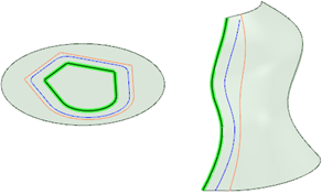
When you are pulling an edge, select this option to create a copy of the edge. The type of offset is determined by whether or not Offset edges by geodesic calculation is selected in Advanced options. This option is selected by default. When this option is selected, all the points on the offset edge are the same distance from the initial edge. In the examples below, the original edge is highlighted in green, the regular offset is shown in orange, and the geodesic offset is shown in blue.
|
|
|
When you are pulling an edge, select this option to pivot the edge along the selected Pull arrow. |
|
Select this option to create a blend between the selected faces, surfaces, or edges when you pull. |
|
|
Rotational blend |
Select this option to create cylinders and cones whenever possible during the creation of a blend. |
|
Periodic blend |
Select this option to go all the way around when blending. |
|
Ruled sections |
Select this option to create straight edges when you pull between three or more surfaces or faces. When you blend between faces, this option has the same affect as selecting the face and its edges. |
|
Revolve Helix |
Select this option to create a helix. |
|
Right-Handed Helix |
Select this option to determine the direction in which the helix is revolved around its axis. |
|
Rotational Rib |
Select this option once you have selected a rotation axis to pull a rib in a rotational direction. |
|
Normal to Trajectory |
Select this option to keep every portion of the swept geometry normal to the sweep trajectory. |
|
|
Select this option to pivot the face on the opposite side of the reference face as well as the selected face. |
Examples
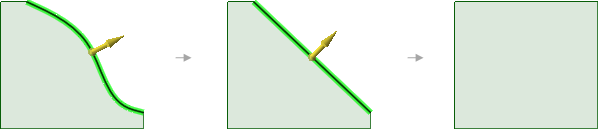
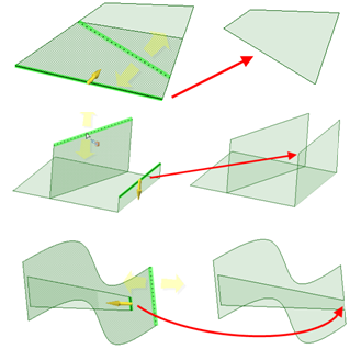
Pulling the edge of a surface first simplifies the edge, then its neighboring edges are extended (or trimmed)
Pulling the edge of a surface while holding Ctrl makes a new surface that is tangent to the edge.
Pulling edges up to other edges with the Up To tool guide
Pulling a point on a surface towards an Alt+clicked vertex
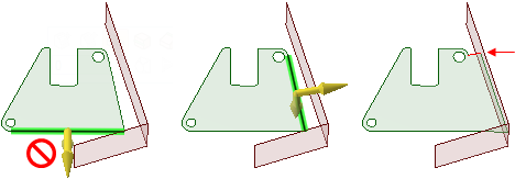
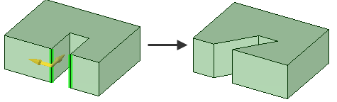
Pulling edges with the Full Pull option. If you select the lower edge of the green surface shown above, you will receive an error because the neighboring surface does not extend past the end of the selected edge. The edge on the right side of the face can be pulled with the option, because the neighboring face extends beyond its length. A new edge is created, which is marked in red in the illustration on the right.
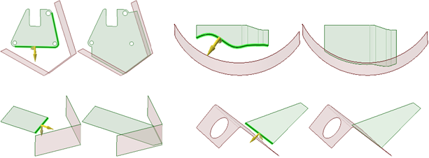
Pulling edges to their nearest neighbor with the Full Pull option
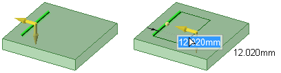
Pulling a sketched line on a planar face creates a surface in the same plane as the face
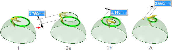
Pulling the edge of a toroidal surface. Three directions are available for pulling.
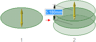
Holding Ctrl while pulling a surface with the Both Sides option creates copies of a surface.
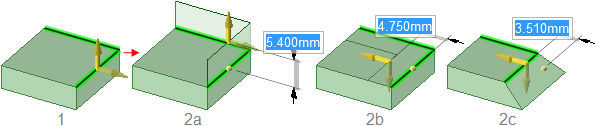
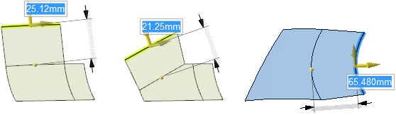
Pulling two edges with the Extrude (2a), Pivot (2b), and Copy edge (2c) options.
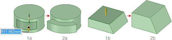
Pulling a face offsets it, and its edges are influenced by neighboring faces.
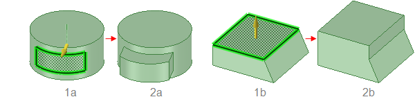
Pulling a face with its edges selected extrudes the face without influence from neighboring faces.
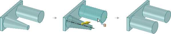
Pulling a conical face Up To a parallel cylindrical face replaces the cone with the cylinder if the axes are close together. Otherwise, the conical face is replaced with a cylindrical face that is coaxial to the cone and has the same radius as the cylinder.
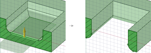
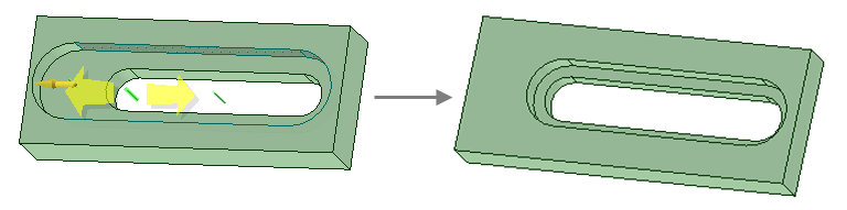
Pulling a pocket with rounded edges down through the bottom of a solid transfers the rounds to the resulting hole.
Pulling a surface up to a reference edge.
Pivot two separate edges together when pulling in one direction.